4.2 文章排序
2020-05-20 更新:无需安装插件或修改源码,主题已经内置排序算法
文章列表默认按照创建时间(如下文章内定义的date)倒序。
使用 top 将会置顶文章,多个置顶文章时,top 定义的值越大,越靠前。
title: 每天一个linux命令
date: 2017-01-23 11:41:48
top: 1
categories:
- 运维
tags: - linux命令
TP-Link TL-WR842N/ND
| V8.0 v8.0 | ? | unsupportable 不可支持 | Only 2M flash (25q16cs1g). SOC Qualcomm Atheros QCA9535. No USB 仅2M闪存(25q16cs1g)。SOC高通Atheros QCA9535.没有USB |
|---|
寄了
记一次详细的TP-link 842n 的刷机过程 —-硬改篇
走走停停,搞了这么久也算是摸清楚这路由器硬改的基本操作了,中间也是一把泪啊,话不多说了进入正题吧
先手准备
- 刀头烙铁一把(我的是可以调温的)
- 高温海绵
- 高温胶带
- 低温焊锡
- 吸锡线
- 助焊剂(很重要)
- 刀片
- 尖嘴钳
- 8Mflash 或者16m 32m都行
10.内存HY5DU121622DTP-43
11.Sop底座一个
12.编程器一个
- 路由器一台,我是在某宝买的二手路由器,一手买不起( ‘-ωก̀ )
祭奠一下被我练手的路由器,你们辛苦了(●’◡’●)ノ
6台路由器4台躺着了,2台飞线应该可以抢救一下,辛苦你们了( ๑ŏ﹏ ŏ๑ )
————————————–伤感的话就到这里了————————————————-
言归正传
这是我的工具图片
开始动手了
烙铁预热先
我的烙铁我一般预热到290度刚刚好,以前傻没有买控温的,而且烙铁还不熟,前两台路由器就是这么玩完的
预热的时候我们就动手把外壳拆了,拆了以后就可以看到具体内容了
开始贴高温胶布,新手建议多贴点,不然到时候一些小零件弄掉了,那就很尴尬了
然后就开始上助焊剂,均匀抹在两边就行,这个有助于锡的流动
抹完助焊剂以后开始用堆锡法拆内存,烙铁头吃点焊锡,然后贴着来回拖动,并且另外一只手用刀片开始撬内存,撬好一个以后另外一个就比较简单的了,来回拖动就可以,然后清理焊盘多余的焊锡,请注意堆锡法时间不要太久,不然焊盘会掉,然后就悲剧了
视频某优有
二手的就是不耐用啊。。。掉了一个以为悲剧了,后面看了一下是一个空脚没有连接什么,没有什么事(淡定淡定)
下一步走起走起
对准针脚然后按住中间对比一下前后左右是否正常,这步不能急要耐心,对其以后对角上锡固定,然后加助焊剂来回拖动,视频某优有
焊接完成 擦擦多余的助焊剂,然后通电,电源灯亮就行了这张图我是插了网线所以三个灯亮
如果焊接完成发现灯全亮,那么只有两个问题就我这台机为例子,
1.你的内存虚焊了,上次为了证明没有虚焊这个问题,我还特地买了一个放大镜(。•́︿•̀。)
2.很坑爹的,内存条颗粒不行,换一个,以前不懂内存都是乱买的,结果十个,一个都用不了,吐血,后面换成海力士就行了。。。。扎心啊
硬改正常后开刷,晚点再写一下软件部分
Flash的焊接过程就不贴出来了,内存搞得定flash就是小菜一碟了,记得用编程器写好h大的不死uboot然后再焊接上去
IP地址设置如下
完美收工
基本上硬件就这样就行了,软件部分我下次再单独写一篇,都是坑啊。。。。
交流技术适当吹水群:667491026 (拒绝大爷公子伸手党)
By:ITdesk
2018年4月2日

自己写的几篇小帖子不清楚的可以去看下 传送门
不过可以继续学习 openwrt
Installation安装
| Version版本 | Model模型 | Supported Current Rel支持的当前版本 | Firmware OpenWrt Install URL标签:OpenWrt Install URL | Firmware OpenWrt Upgrade URL标签:OpenWrt Upgrade URL | Firmware OEM Stock URL固件OEM Stock URL | |
|---|---|---|---|---|---|---|
| v1 | TL-WR842ND | 22.03.5 | Factory image | Sysupgrade image``Sysupgrade图像 | OEM Firmware``OEM固件 | Edit``编辑 |
| v2 | TL-WR842ND | 22.03.5 | Factory image | Sysupgrade image``Sysupgrade图像 | OEM Firmware``OEM固件 | Edit``编辑 |
| v3 | TL-WR842N | 23.05.0 | Factory image``factory image | Sysupgrade image``Sysupgrade图像 | OEM Firmware``OEM固件 | Edit``编辑 |
| v5V5 | TL-WR842N | 23.05.0 | Factory image | Sysupgrade image``Sysupgrade图像 | OEM Firmware``OEM固件 | Edit``编辑 |
Installation via factory web GUI is possible. Just rename the image file to something short before uploading (openwrt-19.07.2-ath79-generic-tplink_tl-wr842n-v3-squashfs-factory.bin to firmware.bin)→ Install OpenWrt (generic explanation)
可以通过工厂WebGUI进行安装。上传前将图像文件重命名为简短的名称(openwrt-19.07.2-ath79-generic-tplink_tl-wr842n-v3-squashfs-factory.bin到firmware.bin)→安装OpenSort(一般解释)
Flash/recovery v1闪存/恢复v1
Using the integrated tftp capability of the router.First, enter failsafe mode:Remove the power plug from the router.Press and hold the WPS/RESET button.Insert the power plug without releasing the RESET button, wait a moment for the USB LED to begin to blink.Release the RESET buttonNo LED besides the one for USB (and maybe for attached Ethernet ports) should be lit.The device now uses the IP 192.168.1.86. It repeatedly tries to download a file named: wr842ndv1_tp_recovery.bin from a tftpd server with the IP 192.168.1.66.The following steps will serve an openwrt firmware image to the device:Download an appropriate firmware file from TP-LINK site.You might need a “stripped” firmware version (without “boot” in the name). See bottom of this page for details and a download link.Rename the file, so it matches the name required by the router: wr842ndv1_tp_recovery.binConfigure your PC lan adapter ip address to IP 192.168.1.66 and connect your computer to one of the LAN ports of the router.Install a tftp server, for windows you can download one from http://tftpd32.jounin.net/ Run the tftp server and browse for the directory that contains the above firmware image. If necessary allow the connection of the server through your PCs firewall, once configured, shutdown the tftp server program, you will launch it again later.If you connect your PC directly to a lan port on the router, be sure to put the router into failsafe mode FIRST (press reset button and plug power cable release reset button after 3 second), and then launch the tftp server, otherwise it might have problems trying to bind to the PC network interface.Right after you launch the tftp server, a couple of blank messages will appear into the log window of the tftp server, this is normal, the third or fourth message will indicate that the process of file transfer is in progress.After some time you will see all LEDs flashing once followed by a normal restart of the routerNow you can install the openwrt factory image of your liking, via the vendor firmware upgrade web page of the router.You could try to flash directly using this method, an openwrt factory image (for this model obviously) to the router, for me it did not work, maybe you have better luck.
使用路由器的集成tftp功能。首先,进入故障保护模式:从路由器上拔下电源插头。按住WPS/WPS按钮。插入电源插头,但不松开USB按钮,等待USB指示灯开始闪烁。松开“关闭”按钮除了USB(可能还有连接的以太网端口)的LED外,其他LED均不应亮起。设备现在使用IP192.168.1.86。它反复尝试从IP为192.168.1.66的tftpd服务器下载名为wr842ndv1_tp_recovery.bin的文件。以下步骤将为设备提供openwrt固件映像:从TP-LINK站点下载适当的固件文件。您可能需要一个“剥离”固件版本(名称中没有“靴子”)。详情和下载链接见本页底部。重命名该文件,使其与路由器所需的名称匹配:wr842ndv1_tp_recovery.bin将PC LAN适配器IP地址配置为IP192.168.1.66,并将计算机连接到路由器的LAN安装一个tftp服务器,对于windows你可以从http://tftpd32.jounin.net/下载一个运行tftp服务器并浏览包含上述固件映像的目录。如果有必要允许通过您的PC防火墙连接服务器,一旦配置,关闭tftp服务器程序,您将在稍后再次启动它。如果您将PC直接连接到路由器上的LAN端口,请务必首先将路由器置于故障保护模式(3秒后按下重置按钮并插入电源线释放重置按钮),然后启动tftp服务器,否则它可能会在尝试绑定到PC网络接口时出现问题。启动tftp服务器后,tftp服务器的日志窗口中会出现几条空白消息,这是正常的,第三条或第四条消息将指示文件传输过程正在进行中。一段时间后,您将看到所有LED闪烁一次,然后正常重启路由器现在你可以通过路由器的厂商固件升级网页安装你喜欢的openwrt工厂镜像。你可以尝试直接使用这种方法闪存,openwrt工厂的形象(对于这种模式显然)到路由器,对我来说,它没有工作,也许你有更好的运气.
Flash/recovery v2闪存/恢复v2
Using the integrated tftp capability of the router.First, enter failsafe mode:I have a question here, why enter failsafe mode, if you are going Failsafe that’s another route, all you have to do is whats next here is a example too http://forum.tp-link.com/showthread.php?81462-How-to-recovery-the-router-when-you-bricked-itRemove the power plug from the router.Press and hold the WPS/RESET button.Insert the power plug without releasing the WPS/RESET button, wait a moment for the Lock LED to come on solid.Release the WPS/RESET buttonConnect PC to one of the router LAN ports.
使用路由器的集成tftp功能。首先,进入故障保护模式:我有一个问题在这里,为什么进入故障安全模式,如果你要去故障安全,这是另一个路线,所有你要做的是什么,接下来这里是一个例子太http://forum.tp-link.com/showthread.php?81462-阻塞路由器时如何恢复路由器从路由器上拔下电源插头。按住WPS/WPS按钮。插入电源插头,但不松开WPS/USB按钮,等待片刻,等待锁定指示灯稳定亮起。释放WPS/WPS按钮将PC连接到路由器的一个LAN端口。
| Device 装置 | IP |
|---|---|
| router IP`` 路由器IP | 192.168.0.86 |
| set your PC IP`` 设置您的PCIP | 192.168.0.66 |
Set PC 设置PC IP:
ifconfig eth0:1 192.168.0.66/24 up
Router repeatedly tries to download wr842nv2_tp_recovery.bin from a tftpd server running on 192.168.0.66.Install tftpd server:
路由器反复尝试从运行在192.168.0.66上的tftpd服务器下载wr842nv2_tp_recovery.bin。安装tftpd服务器:
pacman -S tftp-hpa
Download TP-LINK firmware to tftp root and rename it to wr842nv2_tp_recovery.bin:
下载TP-LINK固件到tftp根目录并将其重命名为wr842nv2_tp_recovery.bin:
mkdir /srv/tftpd
cd /srv/tftpd
wget http://www.tp-link.com/resources/software/TL-WR842ND_V2_130628.zip
unzip TL-WR842ND_V2_*.zip
mv wr842ndv2_en_3_14_2_up_boot(130628).bin wr842nv2_tp_recovery.bin
You might need a “stripped” firmware version (without “boot” in the name). See below for details and a download link.Start tftpd server:
您可能需要一个“剥离”固件版本(名称中没有“靴子”)。请参阅下面的详细信息和下载链接。启动tftpd服务器:
systemctl start tftpd.socket
systemctl start tftpd.service
Router must be in recovery mode before starting tftpd server, otherwise it might have problems trying to bind to the PC network interface.After some time you will see all LEDs flashing once followed by a normal restart of the router.
在启动tftpd服务器之前,路由器必须处于恢复模式,否则在尝试绑定到PC网络接口时可能会出现问题。一段时间后,您将看到所有LED闪烁一次,然后正常重启路由器。
Flash/recovery v3闪存/恢复v3
- Get OEM firmware file from https://www.tp-link.com/en/support/download/tl-wr842n/#Firmware or from mirror https://tplinkforum.pl/t/recovery-dla-routera-tp-link-tl-wr842n-v3/9310.- Rename recovery firmware file to wr842nv3_tp_recovery.bin.- Set up tftp server using IP 192.168.0.66.- Load OEM firmware into router using TFTF client method.- Login into router GUI on 192.168.0.1 with user admin and password admin.- Under menu “System Tools” → “Firmware Upgrade” you can upload Openwrt well known working “factory.bin” image.
- 从https://www.tp-link.com/zh/support/download/tl-wr842n/#Firmware或从镜像https://tplinkforum.pl/t/recovery-dla-routera-tp-link-tl-wr842n-v3/9310获取OEM固件文件。- 将恢复固件文件复制到wr842nv3_tp_recovery.bin。- 使用IP192.168.0.66设置tftp服务器。- 使用TFTF客户端方法将OEM固件加载到路由器中。- 使用用户admin和密码admin登录192.168.0.1上的路由器GUI。- 在菜单“系统工具”→“固件升级”你可以上传Openwrt众所周知的工作“factory.bin”的形象。
Flash/recovery v5闪存/恢复v5
Using the integrated tftp capability of the router.
使用路由器的集成tftp功能。
- Turn off the router.- Connect PC to one of the router LAN ports.- Set your PC IPv4 address to 192.168.0.225/24.- Run any TFTP server on the PC.- Put the recovery firmware on the root directory of TFTP server and name the file tp_recovery.bin- Start the router by pressing power button while holding the WPS/Reset button (or both WPS/Reset and WIFI buttons)- Router connects to your PC with IPv4 address 192.168.0.2, downloads the firmware, installs it and reboots. LEDs are flashing. Now you have OpenWrt installed.- Change your IPv4 PC address to something in 192.168.1.0/24 network or use DHCP to get an address from your OpenWrt router.- Done! You can login to your router via ssh.
- 关闭路由器。- 将PC连接到路由器的一个LAN端口。- 将您的PCIPv4地址设置为192.168.0.225/24。- 在PC上运行任意TFTP服务器。- 将恢复固件放在TFTP服务器的根目录下,并将文件命名为tp_recovery.bin- 通过按住WPS/重置按钮(或WPS/重置和WIFI按钮)的同时按下电源按钮来启动路由器- 路由器使用IPv4地址192.168.0.2连接到您的PC,下载固件,安装并重新启动。指示灯闪烁。现在你已经安装了OpenCart。- 将您的IPv4PC地址更改为192.168.1.0/24网络中的某个地址,或者使用DHCP从OpenSSL路由器获取地址。- 成交!您可以通过ssh登录到路由器。
Unbrick v2
Once you are connected via serial cable to router you will see this prompt
一旦您通过串行电缆连接到路由器,您将看到此提示
wasp>
Then type “printenv” to see environment variables:
然后输入“printenv”查看环境变量:
wasp> printenv
bootargs=console=ttyS0,115200 root=31:02 rootfstype=squashfs init=/sbin/init mtdparts=ath-nor0:128k(u-boot),1024k(kernel),6912k(rootfs),64k(config),64k(art)
bootcmd=bootm 0x9f020000
bootdelay=1
baudrate=115200
ethaddr=0xba:0xbe:0xfa:0xce:0x08:0x41
ipaddr=192.168.1.111
serverip=192.168.1.100
dir=
bc=ap123
lu=tftp 0x81000000 ${dir}u-boot.bin&&erase 0x9f000000 +$filesize;cp.b $fileaddr 0x9f000000 $filesize
lf=tftp 0x81000000 ${dir}${bc}-squashfs&&erase 0x9f120000 +$filesize;cp.b $fileaddr 0x9f120000 $filesize
stdin=serial
stdout=serial
stderr=serial
ethact=eth0
wasp> setenv serverip <TFTP server IP>
wasp> setenv ipaddr <Temp IP address on my network>
wasp> tftpboot 0x80000000 openwrt-15.05-ar71xx-generic-tl-wr842n-v2-squashfs-factory.bin
done
Bytes transferred = 8126464 (7c0000 hex)
Note the hex value in brackets - “(7c0000 hex)”. If you get different value use your value in lines below, otherwise you may irreversibly brick your device.
注意括号中的十六进制值-“(7 c 0000 hex)”。如果您获得不同的值,请在下面的行中使用您的值,否则您可能会不可逆转地砖您的设备。
wasp> erase 0x9f020000 +0x7c0000
wasp> cp.b 0x80000000 0x9f020000 0x7c0000
wasp> bootm 0x9f020000
Back to stock firmware返回到库存固件
→ generic.uninstall
→generic.uninstall
Warning!This section describes actions that might damage your device or firmware. Proceed with care!
警告!本节介绍可能损坏设备或固件的操作。小心行事!
With the TL-WR842N/ND router, there is a catch: the stock firmware is obtained from the OEM: http://www.tplink.com/en/support/download/?model=TL-WR842ND* in case the file name of this firmware file does not contain the word “boot” in it, you can simply revert back to original firmware* in case the file name of this firmware file does contain the word “boot” in it, you need to cut off parts of the image file before flashing it:
对于TL-WR 842 N/ND路由器,有一个问题:从OEM获得库存固件:http://www.tplink.com/zh/support/download/?型号= TL-WR 842 ND* 如果此固件文件的文件名中不包含单词“靴子”,您可以简单地恢复到原始固件* 如果此固件文件的文件名中包含“靴子”一词,则需要在刷新映像文件之前将其部分删除:
The following method applies for the V1, V2, V3(EU) and V5(RU) since the bootloader is the same size.
以下方法适用于V1、V2、V3(EU)和V5(RU),因为引导加载程序的大小相同。
An example of an image file with the word “boot” in it is wr842ndv1_en_3_12_25_up_boot(130322).bin.
一个包含单词”靴子”的图像文件的示例是wr842ndv1_en_3_12_25_up_boot(130322).bin。
Cut the first 0x20200 (that is 131,584 = 257512) Bytes from original firmware:
从原始固件中删除第一个0x20200(即131,584 = 257512)字节:
dd if=orig.bin of=tplink.bin skip=257 bs=512
You should transfer the firmware image to the /tmp folder and revert back to original firmware (if available you can flash the firmware via the web interface as well):
您应该将固件映像传输到/tmp文件夹并恢复到原始固件(如果可用,您也可以通过Web界面刷新固件):
Via the safer method using sysupgrade:通过使用sysupgrade的更安全的方法:
sysupgrade /tmp/tplink.bin
Or you use the mtd method:或者使用mtd方法:
mtd -r write /tmp/tplink.bin firmware
It is also possible to revert to the stock firmware using the method with tftp described in “recovery”. (You still need the firmware image without the boot part).
它也可以恢复到股票固件使用的方法与tftp中所描述的”恢复”。(You仍然需要没有靴子部分的固件映像)。
OEM TP-Link firmware for the TL-WR842N/ND with the boot part removed to revert to the original OEM firmware:* TL-WR842ND V1 TL-WR842ND-V1-stripped.zip* TL-WR842ND V2 TL-WR842ND-V2-stripped.zip
TL—WR842 N/ND的OEM TP—Link固件,移除靴子部分以恢复原始OEM固件:* TL—WR842ND V1 www.example.com* TL—WR842ND V2 www.example.com
Hardware Highlights硬件亮点
| Version版本 | Model模型 | CPU | CPU MHz | Flash MB | RAM MB | WLAN HardwareWLAN硬件 | WLAN 2.4GHz | WLAN 5.0GHz无线局域网5.0GHz | Ethernet 100M ports以太网100M端口 | Ethernet 1Gbit ports以太网1Gbit端口 | Modem现代 | USB portsUSB端口 | |
|---|---|---|---|---|---|---|---|---|---|---|---|---|---|
| v1 | TL-WR842ND | Atheros AR7241 | 400 | 8 | 32 | Atheros AR9287 | b/g/nB/g/n | - | 5 | - | - | 1x 2.0 | Edit``编辑 |
| v2 | TL-WR842ND | Atheros AR9341 | 535 | 8 | 32 | Atheros AR9341 | b/g/nB/g/n | - | 5 | - | - | 1x 2.0 | Edit``编辑 |
| v3 | TL-WR842N | Qualcomm Atheros QCA9531高通Atheros QCA9531 | 650 | 16 | 64 | Qualcomm Atheros QCA9531高通Atheros QCA9531 | b/g/nB/g/n | - | 5 | - | - | 1x 2.0 | Edit``编辑 |
| v5V5 | TL-WR842N | MediaTek MT7628NN联发科MT7628NN | 580 | 8 | 64 | MediaTek MT728NN联发科MT728NN | b/g/nB/g/n | - | 5 | - | - | 1x 2.0 | Edit``编辑 |
Detail info详细信息
| Model 模型 | TL-WR842ND | TL-WR842N(EU) TL-WR842N(EU) | TL-WR842N(RU) TL-WR842N(RU) |
| Version 版本 | v1 | v2 | v3 | v5 V5 |
| —————————————— | ———————————————————————- | ——————————————————————————– | ————————————– |
| Architecture: <br/> 体系结构: | MIPS 24Kc V7.4 | MIPS 74Kc V4.12 | MIPS 24Kc | MIPS 24KEc V5.5 |
| Manufacturer: <br/> 制造商: | Atheros | Qualcomm Atheros | MediaTek 联发科 |
| Bootloader: <br/> 引导加载程序: | U-Boot | U-Boot? U-Boot? |
| System-On-Chip: <br/> 片上系统: | Atheros AR7241 | Atheros AR9341 | Qualcomm Atheros QCA9531-BL3A 高通Atheros QCA9531—BL3A | MediaTek MT7628NN 联发科MT7628NN |
| CPU Speed: <br/> CPU速度: | 400 MHz <br/> 四百MHz的 | 535 MHz <br/> 535 MHz的 | 650 MHz <br/> 650 MHz的 | 580 MHz <br/> 580 MHz的 |
| Flash chip: <br/> 闪存芯片: | Spansion S25FL064P (FL064PIF) <br/> Spansion S25FL064P(FL064PIF) | Winbond 25Q64FV or Spansion S25FL064 Winbond 25Q64FV或Spansion S25FL064 | Winbond 25Q128CS16 华邦电子25Q128CS16 | SPI 25Q64CS16 |
| Flash size: <br/> 闪光灯尺寸: | 8 MiB | 16 MiB | 8 MiB |
| RAM chip: <br/> RAM芯片: | A3S56D40FTP -G5 | Winbond W9425G6JH-5 华邦W 9425 G6 JH-5 | Zentel A3R12E40CBF-8E | Zentel A3R12E40DBF-8E Zentel A3R12E40DBF—8E |
| RAM size: <br/> RAM大小: | 32 MiB | 64 MiB | 64 MiB |
| Wireless <br/> 无线 | Atheros AR9287-bl1a | Atheros AR9341 | Qualcomm Atheros QCA9531 高通Atheros QCA9531 | MediaTek MT7628NN 联发科MT7628NN |
| Antenae(s) <br/> ae(s) | 2 removables 2例拔除 | 2 non-removable 2个不可移动 | 2 non-removable 2个不可移动 |
| Ethernet: <br/> 以太网: | 4 LAN, 1 WAN 10/100 <br/> 4个局域网,1个广域网10/100 |
| USB: <br/> USB接口: | 1 x 2.0 |
| Serial: <br/> 序列号: | Yes <br/> 是的 |
LAN-port mapping局域网端口映射
This is only tested on a V2 device.这仅在V2设备上进行测试。
Note: On (EU) version seems to be 1-4, 2-3, 3-2, 4-1, best check before connecting a cable and using cable detection (on luci>network>switch).
注意:在(欧盟)版本似乎是1-4,2-3,3-2,4-1,最好在连接电缆和使用电缆检测(在luci网络交换机上)之前进行检查。
| chassis port 机箱端口 | internal-port 内孔 |
|---|---|
| WAN (blue)``WAN(蓝色) | CPU: eth0 CPU:eth0 |
| 1 (yellow) 1(黄色) | Switch eth1; Port 2 交换机eth1;端口2 |
| 2 (yellow) 2(黄色) | Switch eth1; Port 3 交换机eth 1;端口3 |
| 3 (yellow) 3(黄色) | Switch eth1; Port 4 交换机eth1;端口4 |
| 4 (yellow) 4(黄色) | Switch eth1; Port 1 交换机eth1;端口1 |
Note: the default lan interace (VLAN 1) is preconfigured to use eth0 physical interface (cpu untagged in switch configuration). If you want to use more than one VLAN connected to CPU, then CPU port must be tagged. In this case you need to change lan interface from eth0 to eth0.1 (for VLAN id = 1). If using luci, remember to do both changes (switch and lan) before applying any of them.
注意:默认的局域网接口(VLAN1)已预先配置为使用eth0物理接口(交换机配置中未标记cpu)。如果您想使用多个VLAN连接到CPU,则必须标记CPU端口。在这种情况下,您需要将lan接口从eth0更改为eth0.1(对于VLANid = 1)。如果使用luci,记住在应用任何一个之前都要做两个更改(switch和lan)。
Flash LayoutFlash布局
Please read the article flash.layout for a better understanding. It contains a couple of explanations. Then let’s have a quick view at flash layout of this particular device:
请阅读文章flash.layout以更好地理解。它包含了几个解释。然后,让我们有一个快速查看在闪存布局这个特定的设备:
| TP-Link WR842ND Visual Flash Layout OpenWrt 12.09`` TP-Link WR842ND Visual Flash Layout OpenCart 12.09 |
|---|
| Offset 偏移 |
| x64KiB Blocks x64KiB数据块 |
| TP-Link WR842ND Flash Layout OpenWrt 12.09`` TP-Link WR 842 ND闪存布局OpenSort 12.09 |
| Layer0 层0 |
| Layer1 |
| Layer2 |
| mountpoint |
| filesystem 文件系统 |
| Layer3 |
| Size in KiB 大小为KiB |
| Name 名称 |
| mountpoint |
| filesystem 文件系统 |
ART = Atheros Radio Test - it contains mac addresses and calibration data for the wifi (EEPROM). If it is missing or corrupt, ath9k won’t come up anymore.
ART = Atheros无线电测试-它包含wifi的mac地址和校准数据(EEPROM)。如果它丢失或损坏,ath 9 k将不再出现。
Here is a LibreOffice Calc ODS for better understanding: http://ubuntuone.com/5eT1OJweXjF6aa3lMciaLw .
这里有一个LibreOffice Calc ODS,可以更好地理解:http://ubuntuone.com/5eT1OJweXjF6aa3lMciaLw。
GPIOsGPIO
→ port.gpioThe AR9341 v3 platform used in the TL-WR842ND provides 23 GPIOs. Some of them are used by the router for status LEDs, buttons and to communicate with the RTL8366RB. The table below shows the results of some investigation:
→port.gpioTL-WR 842 ND中使用的AR 9341 v3平台提供23个GPIO。路由器将其中一些用于状态LED、按钮以及与RTL 8366 RB通信。下表显示了一些调查的结果:
| GPIO | Common Name 通用名称 | Usage 使用 |
|---|---|---|
| 4 | USB Power USB电源 | set to 0 to turn off the usb port, 1 to turn on 设置为0关闭usb端口,1打开 |
AR7241 rev 1 (TL-WR842ND v1):AR 7241版本1(TL-WR 842 ND v1):
| GPIO | Common Name 通用名称 | Usage 使用 |
|---|---|---|
| 6 | USB Power USB电源 | set to 0 to turn off the usb port, 1 to turn on 设置为0关闭usb端口,1打开 |
Photos照片
Opening the Case打开机箱
Loosen the screws under the two rubber foots at the back of the device before (forcefully) pulling the upper and lower shelfs apart.
在(用力)拉开上、下搁板之前,松开设备背面两个橡胶底脚下的螺钉。
Serial connector串行连接器
| TL-WR842ND v1.0 Serial-InterfaceTL-WR 842 ND v1.0串行接口 | TL-WR842ND v2.1 Serial-InterfaceTL-WR 842 ND v2.1串行接口 | TL-WR842N(RU) v3 Serial-InterfaceTL-WR 842 N(RU)v3串行接口 | TL-WR842N(RU) v5TL-WR842N(RU)v5 |
Serial串行
Pinout引脚说明
| 1 | 2 | 3 | 4 | V1 | V2.1 v2.1 |
|---|---|---|---|---|---|
| TX | RX | GND | VCC | SJ1 | JP1 |
Pin 1 is clearly marked on the board.引脚1在板上有明确的标记。
To get the serial connection work reliably, you may have to connect a 10k pullup resistor between the TX and the 3.3V pin (same problem as described in TL-MR3420). For some users the V2.1 models did not need this pullup resistor.
为了使串行连接可靠地工作,您可能必须在TX和3.3V引脚之间连接一个10 k上拉电阻(与TL-MR 3420中描述的问题相同)。对于某些用户,V2.1型号不需要此上拉电阻。
The TX pin is connected via a 10k resistor to ground and via a 100nF capacitor to the serial output of the SoC. This gives a 2.5Vpp swing centered on ground. While this may work with some serial adapters, it is on the low side for most. An advantage of this connection scheme is that it protects the serial output to some degree.
TX引脚通过一个10k电阻接地,并通过一个100nF电容连接到SoC的串行输出。这提供了一个以地为中心的2.5Vpp摆幅。虽然这可能适用于某些串行适配器,但对于大多数串行适配器来说,这是偏低的。这种连接方案的一个优点是它在一定程度上保护了串行输出。
For WR-842N v3, to activate serial interface, you need to solder two resistors (or jumpers) according this photo (marked as red circles):
对于WR-842 N v3,要激活串行接口,您需要根据此照片焊接两个电阻(或跳线)(标记为红色圆圈):
The right settings for accessing the serial console are as follows:
访问串行控制台的正确设置如下:
Bits per second: 115200Data bits: 8Stop bits: 1Parity: NoneFlow control: None
每秒比特数:115200数据位数:8停止位:1奇偶校验:无流量控制:无
Password to get into uboot prompt is tplPassword to get root login is 5up
进入uboot提示符的密码是tpl获得root登录的密码是5up
For TL-WR842n v.3 serial console/ssh access Login: root Password: sohoadmin
用于TL-WR 842 n v.3串行控制台/ssh访问登录名:root用户名:
Power功率
General一般
This device has two main power regulators, one 12V→3V3 for the CPU, memory, wireless and one 12V→5V for USB.
该设备有两个主电源调节器,一个12V→3V3用于CPU,内存,无线和一个12V→5V用于USB。
Main 3V3 Power主3V3电源
This is delivered by a switching regulator with up to 2A at 3V3 output. Power is drawn from external input over one 1A Schottky diode (SS14), with a voltage drop of max .45V at 1A. It should be perfectly safe to draw an additional 100-200mA for your own additions from 3V3.
这是由一个开关稳压器提供高达2A的3V 3输出。电源是从外部输入超过一个1A肖特基二极管(SS 14),与最大的压降0.45V在1A。它应该是完全安全的提请额外的100- 200毫安为您自己的补充从3V 3。
USB PowerUSB电源
USB power is derived from the 12V input over two SS14 Schottky diodes, the one also feeding the 3V3 regulator and an additional one. The output regulator is capable of delivering up to 1.5A, but there is a USB current switch/limiter that limits output current to 1A (and goes into 50% duty-cycle on/off in addition after about 200ms on short-circuit).
USB电源来自两个SS 14肖特基二极管上的12 V输入,其中一个还为3V 3稳压器和另一个供电。输出调节器能够提供高达1.5A的电流,但有一个USB电流开关/限制器,将输出电流限制在1A(并且在短路约200 ms后进入50%占空比开/关)。
It should be fine to draw something like 700mA long-term from 5V USB and up to a bit less than 1A briefly. This is enough to spin-up and power most external 2.5“ USB HDDs. You can try it out. The worst that can happen is that it does not work. The USB power-switch is fully protected and the regulator has reserves, as it uses an external PNP power transistor and has its own over-current protection at 1.1A.
从5V USB长期汲取700mA之类的电流,并短暂地汲取不到1A的电流,应该没问题。这足以启动大多数外部2.5”USB HDD并为其供电。你可以试试最糟糕的情况是它不起作用。USB电源开关受到充分保护,稳压器具有储备,因为它使用外部PNP功率晶体管,并具有1.1A的过流保护。
I did run it at 750mA current draw from USB for half an hour without the regulator getting too warm. What I measured was 10C below the main SoC. The external 12V/1A PSU should also be fine with these loads. Still, if anything blows up in your face, or your house burns down, I am not responsible…
我确实运行它在750毫安的电流提请从usb半个小时没有调节器变得太暖。我测量的是低于主SoC的10 C。外部12 V/1A PSU也应该可以承受这些负载。不过,如果有什么东西在你面前爆炸,或者你的房子被烧了,我可不负责…
Tags
How to add tags
如何添加标签
ar9341 AR9341 fastethernet FastEthernet 5port 5端口 usb USB 1usb 1USB usb2.0 USB2.0 serial 串行 integrated 集成 802.11bgn 1wnic ar9287 AR9287 ath9k 2ant detachableantenna 可变天线 32RAM 8Flash mips MIPS mips32 MIPS32 24kc ar7241 AR7241 12v powered 12v供电
- Last modified: 最后修改日期: 2024/04/29 22:042024/04/29 22:04
- by 通过 jalakas
笔记
我应该是v8 Qualcomm Atheros QCA9535 v3是 QCA9531
第一:QCA9531介绍
QCA9531是一款高度集成且功能丰富的IEEE 802.11n 2x2 2.4 GHz的WiFi芯片,SKYLAB基于QCA9531方案研发推出两款QCA9531的WiFi模块。
SKW97/SKW99都是基于QCA9531方案研发推出的AP/Router
WiFi模块,性能优异,双天线设计,2T2R模式下,支持高达300Mbps
PHY数据传输速率,工业级设计,具有功耗低,发热量低的特点,支持LAN端口和WAN端口,且支持较多的3G/4G模块型号。
模块只需要一个外部3.3V电源供电即可正常工作,模块支持桥接模式、AP客户端模式、网关模式,符合FCC / CE / IC / RoHS认证标准。
第三:QCA9531 WiFi模块特点
符合IEEE 802.11 b/g/n无线标准协议;
在2T2R模式下,支持300Mbps PHY数据传输速率;
DDR2内存高达1024Mb,Flash内存可扩展至128Mb;
模块支持4个LAN端口和1个WAN端口;
支持UART WiFi透明传输
模块自带的USB接口支持4G模块,兼容市面上主流的4G模块。除此之外,还可以接USB磁盘、USB 3G / 4G加密狗、USB摄像头等USB 2.0从机设备;
安全性方面:WEP64 / 128,TKIP,AES,WPA,WPA2,WAPI;
可提供OpenWRT SDK 技术支持;
ver 7 by https://www.mydigit.cn/thread-284990-1-1.html

就一个DC-DC,看着就不咋地的电解电容。元件很少。

三贱客之一,第7版缩水的相当厉害。

输入9V换成立创商城海外代购的16V,1000uF电容。看着就比原装的好。3.3V输出换成3个钽电容,合计540uF。

背面也再并联10uF贴片电容。大家都说供电有问题就容易不稳定。

V7版本是2M的FLASH加8M的RAM太小了,不换硬件是刷不了第三方固件的。这个路由器不太抽风,信号不错,但是功能也极少。而且不知道为什么,隔一段时间,可能几小时,我的手机就断联了,但是手动重新连接也能上网。完全不知道为什么断联。但是每天都断几次。

主控是高通的QCA9533,经百度,有适配的固件和BREED用。

犹豫两三天,狠心花了7大洋,买了64M的RAM和16M的FLASH。型号都是按网上说的买的。据说海力士的RAM兼容性好。买了之后才知道型号后边的后缀还有幺蛾子,FLASH有不同通信速率的,我买的低速的,不过无所谓。

根据网友经验,先换难度大的RAM,如果失败,就不用折腾后边了。

这玩意旁边的电阻电容太近了,而且太小了,0402还是0201的?弄掉了就惨了。于是贴好铝胶带保护,怕耐高温胶带不粘。

风枪350度不太行,调到400度,风速1/3 。费了点劲,拆了下来。但是悲剧了,胶带的胶用酒精都除不掉。

开机,有WIFI,没有翻车,哈哈。可以进行下一步,换FLASH了。

前几个月买的编程器。为了硬刷二手惠普Z420工作站的BIOS。研究好几天,提取原机BIOS,配合官网BIOS,再配合NVME微码还是驱动啥的,3个整合成一个,才能让Z420的V1版支持E5-V2的CPU和让NVME硬盘从PCIe启动。为此还看了几十页英文资料。把这个16M的FLASH焊上去,准备刷OPENWRT固件。

我下载的这个固件是自带BREED的,省心了。擦除,查空,编程,校验搞定。

贴胶带保护元件。

拖焊拆FLASH下来。

全部搞定。


主控加个散热器,用很薄的704硅胶固定。一切折腾完很好用,WIFI信号很强。至于是否解决了断联问题,还要继续观察。用了几个小时还没出问题。(后续更新:确实不再断联了。)还有一个问题,我用网件中继过来的网速假如能到10M,加上腾达或者TP-LINK二级路由之后,测速只有8M左右。反复对比好多次,都有明显的网速损失。测速都是用的电脑有线连接路由器。这个网速损失太大了吧。即使刷了OPENWRT还是这样。好像我用网件当二级路由的时候损失没这么大啊?难道是因为这2个路由器没有千兆网口?但是百兆网络不至于需要千兆网口才能跑满吧?百思不得其解!!!!!!!!!
太费事了,真不如买一个。这就是电子现状
【SuperWRT】从此2M Flash的设备有救了,已有wr886n(多拨)版本
SuperWRT一个全新的第三方路由系统,Tiny版本支持2M Flash的设备。目前完成初步开发,进入测试阶段。测试阶段发布了TP-Link的wr886n的测试版本。
与测试版本配套的还有wr886n可用的uboot。
uboot支持以下功能:
开机长按Reset可进行网页刷机。
有DHCP服务器功能,可自动给PC分配地址。
通过oplogin.cn或oplogin.com可登录刷机网页,再也不用记IP了。
支持TP-LINK引导原生系统启动。
SuperWRT Tiny V0.0.6版本支持以下功能:
静态地址、动态地址、PPPoE拨号连接。
PPPoE进行多次拨号叠加。
支持TP9343的WLAN功能。Tiny版本仅可做AP。
支持根据MAC地址限速,更支持新用户默认限速,支持对限速用户进行流量整形。(SuperWRT完全自己实现的模块)
支持WAN口MAC地址克隆或修改。
支持虚拟服务器功能(即DNAT)。
支持PPtP virtual**功能,支持指定服务器端口号。
响应式管理界面。
首页:
用户管理
网络及系统配置:
应用和PPtP virtual**应用配置:
配置向导。
新手上传文件大小受限了。
先在这里传一个boot了,挣点积分了。
其它的下载链接及说明:
http://superwrt.com/download/test/
注意:一定要用v5的设备,我下到v3设备的固件,发现Flash分区的格式不太一样。所以,v3及以前版本的用户先不要刷,不然会丢失校准信息。
http://www.superwrt.com/wiki/devices/tplink/start 我想做的别人都已经做过了
不少网友为了提取TL-WR886N V5的art伤透脑筋。用了坛里的art可能信号差的不要不要的。TL-WR886N V5的art并不在最后的64K(无语)!!!通过论坛的思考,正确的找到了TL-WR886N V5 编程器固件art所在位置,不敢独享。
废话少说,进入正题:
1、 当然是通过各种手段得到的TL-WR886N V5原厂固件(2M)编程器固件啦。
2、 用WinHex或HxD打开原厂固件,找到20800~20C3F ,这个区间才是art有用的数据。把它复制下来,备用。
3、 用WinHex或HxD新建一个64K的art文件,从1000开始粘贴并写入刚才复制的art有效数据。
4、 确认art文件大小是否为64K,到此大功告成。
如有不妥的地方请多多指教。。。。
另附上本人提取的art,但并不一定都通用。
TL-WR886N一般都是2M闪存,16M内存.
但要想跑OpenWRT内存16m启动不起来(本人开始只换了16M闪存(W25Q128FV),breed能运行起来于是刷入了openWRT,结果重启就是网卡识别不了192.168.10.X的 网段,只能识别到的是什么169开头的网段,最后换上64M的内存即可。)
最低也的 32m,最好更换成64M内存,几块钱一个淘一下很便宜这个。(内存颗粒 HY5DU121622DTP-D43 DDR64M16位)
1.提取2M闪存art,art文件简单来说就是为了能够启动无线的设置文件。方法如下的link。
TL-WR886N V5(TP9343)编程固件art的提取
- 下载对应,Breed选择breed-tp9343.bin
Breed地址:https://breed.hackpascal.net/
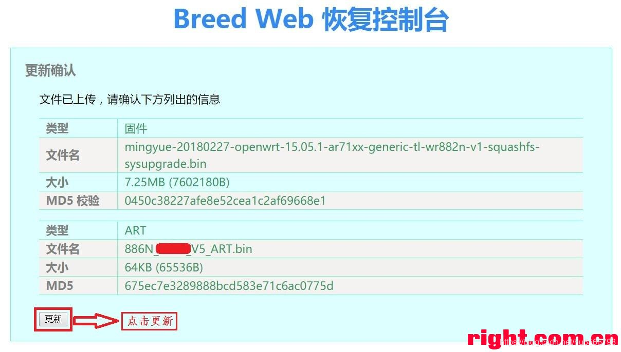
3,下载对应OPenWRT固件8M版本选择mingyue-20180227-openwrt-15.05.1-ar71xx-generic-tl-wr882n-v1-squashfs-sysupgrade.bin;
明月OpenWRT文件下载地址

4.烧录breed到16M的闪存,把2M闪存卸下,把烧录好16M闪存焊接上路由上面去。
刷OpenWRT
- 路由器断电,用网线连接电脑与路由器的LAN口(注意,是一排4个网口里的任意一个,不是橙色的WAN口)
- 用针按住复位键不要松手,接上电,直到看到路由器灯一直闪烁再松手。(其实不用按复位键也能自动进入闪烁模式的)
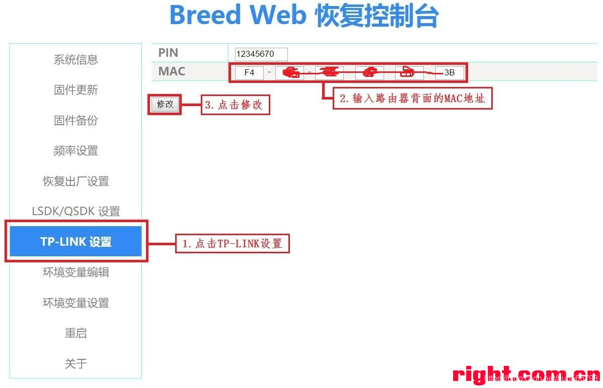
- 进breed恢复模式,打开浏览器登录192.168.1.1 ,
- 修改MAC地址,点击TP-LINK设置,PIN不用管,看MAC地址是否与路由器背面的MAC地址一致,一般改过一次之后都不需要 再次修改,可直接进行下一步。
- 刷固件与wifi信号配置文件,点击左侧的固件更新,然后勾选固件和ART,分别点击浏览选择文件后点击上传:
(1) 固件选择8M版本的mingyue-20180227-openwrt-15.05.1-ar71xx-generic-tl-wr882n-v1-squashfs-sysupgrade.bin;
(2) ART选择886NV5-0D04原厂ART.bin
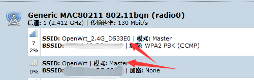
wifi的默认名称:
成功刷机后,会发现OpenWrt_2.4G
OpenWrt这连个网络。一般只有OpenWrt_2.4G可连可用,默认wifi密码rootroot。
- 修改路由登录密码
系统”中的“管理权”如下图:

6.进度条走完后一定要等到路由器自动重启完成之后,路由器才能断电,否则会刷写失败,进不去路由器,又要从头再刷一次。
路由器(路由器始终还是用网线连着电脑,网线是必须的不像小米刷机那样可以用无线来刷机)自动重启完成之后(路由器的灯是先常亮然后就是闪烁,闪烁大概1分钟就一直常亮就一般都是成功刷机了,电脑网卡会成功识别到192.168.10.X的网段),打开浏览器进入192.168.10.1 ,初始账号和密码是root, 无线的密码是rootroot
  按OpenWRT设置步骤对路由器进行重新设置完成即可!自行百度明月OP设置
故障剖析:
本次硬改主要的困难,是64M内存的焊接,拆焊新手建议是用风枪。拆焊后用烙铁推平焊盘上的焊锡,这样新的内存放置比较容易对准焊盘。有时候确实不对得太准,引脚和焊盘有点偏差都是可以焊接成功上去的。第一次焊接上机出现了上电,灯全亮(所有灯包括网口灯都亮)网卡完全识别不了。重新细致再补焊一下内存让每个引脚都沾锡,故障就排除(网口灯不会自动一直亮了,只有插上网线才会亮才是正常的。)
从灯的闪烁判定刷机是否成功:
路由器的灯是先常亮然后就是闪烁,闪烁大概1分钟就一直常亮就一般都是成功刷机了
转载请注明来源,欢迎对文章中的引用来源进行考证,欢迎指出任何有错误或不够清晰的表达。可以在下面评论区评论,也可以邮件至 3400639399@qq.com

